When developing a duct shaft layout, architects must account for steel supports, duct take-offs, dampers, and insulation. The following diagrams provide general clearances, but consult with an HVAC engineer for the needs of a particular system.
General Layout
Provide 9" from the sheet metal to the inside face of a shaft.
Provide 12" from the sheet metal to the inside face of a shaft on sides where there is a duct take-off. See the note below for information about dampers, which can require up to 24" of clear space.
Provide 9" between ducts (sheet metal to sheet metal).
Relative to Structure
The above diagram addressed the distance from the face of the duct to the inside face of the shaft; however, the designer must also consider structure or deck/slab edges.
While maintaining the above dimensions, also provide a minimum of 6" from the face of the duct/slab to the deck edge. The section diagram below shows these clearances.
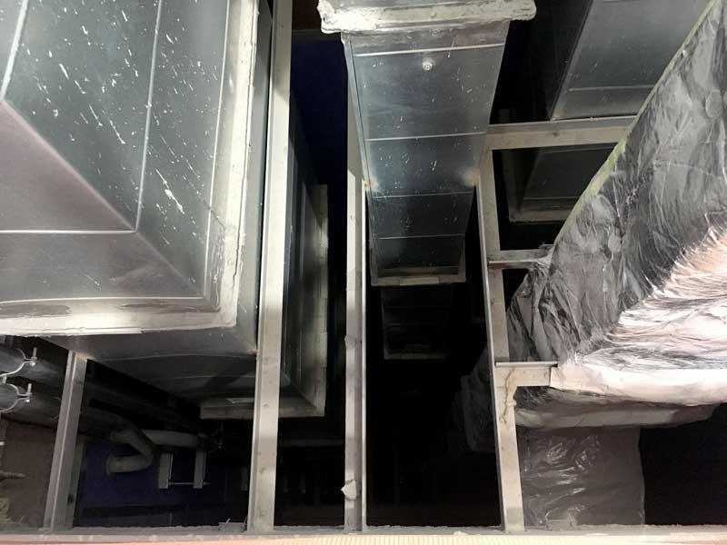
While the diagram above shows the support steel sitting on top of the slab edge, the supports can also be attached directly to the face of the slab edge if there is a steel bent plate to receive a weld. The photograph below shows this type of condition.

Dampers
Consult with the damper manufacturer for dimensional requirements. Fire dampers generally require 15" between the duct face and the inside face of the shaft wall. Combination Fire and Smoke dampers can require up to 24" of clear space between the duct face and the inside face of the shaft wall. In addition, the damper must be accessible so that the unit can be reset after it has been closed.


